In short: The RAG pattern for LLMs can be evaluated using QA pairs. Creating a "golden" dataset is expensive, but an auto-generated "silver" dataset can help guide RAG's development and initial retrieval process. In this article, one approach is proposed.
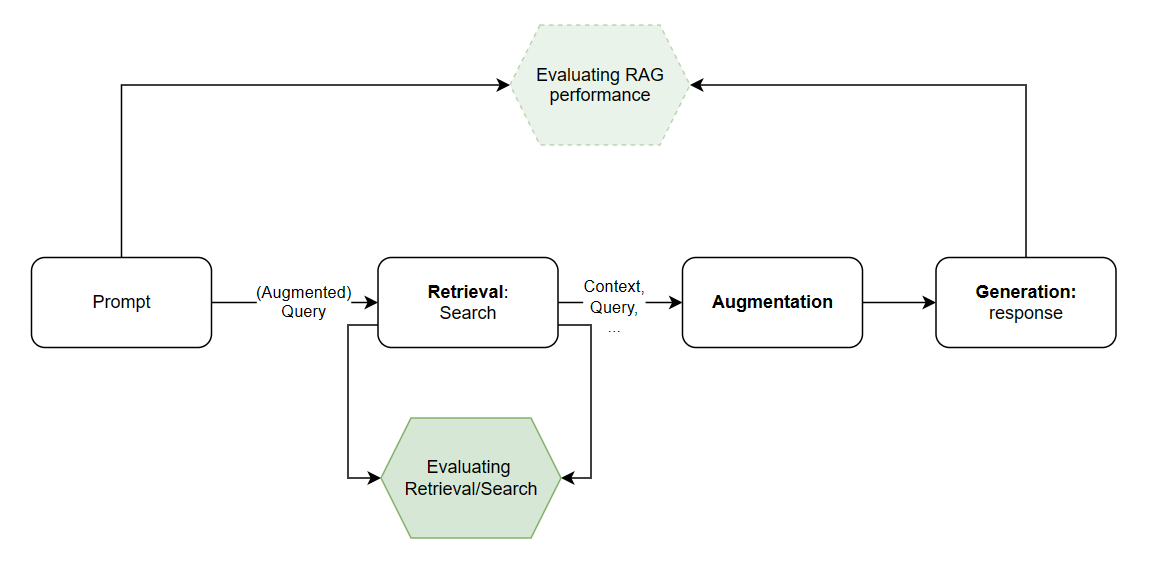
Working on the RAG (Retrieval, Augmentation, Generation) pattern for LLMs allows for using the LLM's natural language capabilities as a reasoning-capable frontend for providing context outside of the training data. It is crucial, however, to be able to evaluate the RAG pattern using question-answer pairs such that the built solution matches both real-world usecases and the quality of generated answers can be verified. This is especially difficult given domain specific and highly-technical documentation and context. Often, this is tackled using a golden dataset which aims to closely match actual user scenarios as well as a broad range of possible question/answer pairs. A golden dataset might consist of a question, a context and an ideal answer. The golden dataset is quite costly to generate and maintain as subject matter experts (SMEs) need to be highly involved in creating the dataset. This means it is often practically infeasible to generate a wide-spanning golden dataset for large amount of documentation.
While a nontrivial challenge, it is still desireable to have a golden dataset (co-)created by SMEs so that evaluation metrics closely match real-world performance. In addition to the golden dataset, however, the use of an automatically generated dataset (a synthetic or silver dataset) can offer a variety of benefits and uses. In our ongoing engagement, it will help us steer the development of (various parts of) our RAG solution while the golden dataset is still being built. Arguably, we cannot prove the relationship between a silver dataset and real world (engineering) use-cases, but steering the RAG ship with a silver compass is better than sailing blind. We will be using a silver dataset not only for evaluating the end-end RAG solution (i.e., from user query -> answer), but also for the performance of just the retrieval (RAG). For context, we currently use Azure Cognitive Search with hybrid searching (that is, both vector search and regular text search).
Retrieval evaluation
Measuring performance of retrieval using the silver dataset (trivially) works as follows:
- Generate a set of question-answer pairs. Take note of the location (file, page, or section) of the retrieved information.
- For each question: 1. send the question (query); 2. check if your retrieval (search) finds the correct section in the reference document.
- This step is crucial as retrieval is the most fundamental part of RAG. Without a proper context, the LLM cannot ground its answer and chances of hallucinations increase.
- The naive metric: count the number of correct answers. Other metrics exist, but we won't be discussing them in this post.
This process can be automated, and for instance even be added to pipelines to automatically (sanity) check retrieval performance.
QA generation
Some methods exist to automatically generate QA-pairs for (technical) documentation. They include a sequence-to-sequence qa generator on huggingface for which I am not impressed by the performance of the generated QA pairs, and ragas testset generation (link to relevant code). Interestingly, the Ragas approach seems to make use of a critque LLM which decides whether or not the generated QA-pairs are useful.
Personally, I have found the simple approach of a strong prompt in addition to an LLM call with the context to work best. Using GPT4-32k and the prompt which follows, I have been able to reliably generate QA-pairs which are relevant to the context. Most importantly, the instruction to only generate technical question in addition to prompting the LLM to respond with None in certain cases seems to work well in ensuring relevant questions are generated. The latter is important since not all contexts (i.e., text-windows from the origin document) might contain information which is relevant to generate a QA-pair for in the first place.
The prompt is:
You are an AI whose purpose it is to generate question and answer pairs.

It is crucial these question answer pairs are specfic to the context the USER will give you and are related to TECHNICAL content, such that these question answer pairs cannot be retrieved otherwise. DO NOT make up questions and answers that are not related to the context the USER will give you, this will be heavily penalized.

If no technical question can be formulated, it is acceptable to return none. You are expected to return the question pair in JSON like so:

{
    "question": "What is the operating pressure of TK-3413?",
    "answer": "The operating pressure is 1.5 bar."
}

Examples:
USER:
"TK-3413 is a pressure vessel that is used to store water. It is used in the production of the Ford F-150. The operating pressure is 1.5 bar."
AI:
{
     "question": "What is the operating pressure of TK-3413?",
     "answer": "The operating pressure is 1.5 bar."
}
USER:
"The captial of France Paris, in Paris lays the Eiffel Tower. The Eiffel Tower is 324 meters tall."
AI:
{
     "question": "NONE", # No technical question can be formulated, and any search engine can retrieve this information, so None must be returned.
     "answer": "NONE."
}
A simple implementation can be found on my monorepo which includes a crude implemention of chunking PDFs followed by the QA generation.
Example technical document QA generations
The table below gives a sample of QA-pairs generated from pages 10~30 in the Ford Shop Manual for Series 2N 8N 9N (Expired copyright).
View results (click me)
| Question | Answer |
|---|---|
| What is the purpose of the Tractor Manual Archive? | The Tractor Manual Archive is a repository of Tractor Manuals that are typically out of Copyright, and are now in Public Domain. It also includes manuals that have Copyright holder permission to be included. It aims to preserve useful history. |
| What is the firing order of the engine in Tractor Models 2N, 8N, 9N? | The firing order is 1-2-4-3. |
| What is the material of the production cylinder sleeves for 8N after 433577? | The material of the production cylinder sleeves for 8N after 433577 is Iron. |
| How can the front axle be adjusted on model 8N? | The front axle can be adjusted to vary tread width. However, the steering linkage must be readjusted when tread width is changed. |
| What are the steps to adjust the sectors of the steering gear in early model 9N without removing the steering housing? | To synchronize sectors without removing steering housing, disconnect both drag links at steering arms and move left arm rearward as far as possible, and right arm in the opposite direction to un-mesh gears. Re-engage both sectors with steering shaft pinion and check synchronism by observing whether steering arms are parallel and point slightly rearward, when gear is in mid or straight ahead position. Reconnect drag links and adjust same if necessary. |
| What is the correct pull required to rotate the steering wheel through the mid or straight forward position after making adjustments? | The correct pull required to rotate the steering wheel through mid or straight forward position is not less than 2-1/2 or more than 6 pounds with drag links disconnected. |
| What is the correct bearing adjustment for the steering wheel in the gear assembly? | Bearing adjustment is correct, when pull required to rotate steering wheel through center or straight forward position is 1-1/2 pounds with drag links disconnected and sector mesh adjustments loosened. |
| What is the correct adjustment for the sector arms backlash on a model 8N tractor? | Correct adjustment is when 2 to 3 pounds of pull is required to maintain the steering wheel in motion through the straight ahead or mid-position, drag links disconnected and opposite sector adjustment backed off. After adjusting the right hand sector as just mentioned, repeat the procedure on the left sector. A pull of 2-1/2 to 6 pounds (measured at rim end of wheel spoke) should be required to maintain the steering wheel in motion through the mid or straight-ahead position. |
| What is the correct toe-in adjustment for the tractor? | Correct toe-in is 0 to 1/4 inch. |
| What is the correct valve tappet clearance for inlet and exhaust valves? | The correct valve tappet clearance cold is .010 to .013 for inlet and from .014 to .016 for exhaust valves. |
| What is the correct valve tappet clearance for inlet and exhaust valves? | Correct valve tappet clearance is .010 - .012 cold for inlet and .014 - .016 cold for exhaust valves. |
| What is the stem to guide clearance wear limit for inlet and exhaust valves in early production guides used in models 2N, 9N and 8N tractors? | The stem to guide clearance wear limit is .005 for inlet and .006 for exhaust valves. |
| What is the required gap or end clearance for engines with free type exhaust valve rotators? | A gap or end clearance of .0002 to .004 must exist between cap and end of valve stem. |
| What is the recommended bearing clearance for the camshaft? | The recommended bearing clearance is .001 - .002. |
| What is the difference in outside diameter between iron and steel sleeves used in engines? | The outside diameter of iron sleeves is approximately .098 larger than steel sleeves. |
| What is the recommended speed to drive the hone when final sizing the sleeves? | A drill with a speed of 250 to 450 rpm should be used to drive the hone. |
| What is the length of the piston pins for aluminum and cast steel pistons? | Pins for aluminum pistons are 2.844 long and pins for cast steel pistons are 2.972 long. |
| What is the recommended running clearance of gear shaft in the oil pump's bushing? | The recommended running clearance of gear shaft in bushing is .0005 - .0015. |
| What is the desired clearance for a new shaft in the drive gear shaft bushing? | The desired clearance for a new shaft in the drive gear shaft bushing is .0005 - .0015. |
| What is the correct clearance between washer and fork base in the governor assembly? | The correct clearance between washer and fork base should be from .220 to .230. |
| What is the process to check the clearance between the washer and the fork base? | To check the clearance between the washer and the fork base, clamp the shaft and driver assembly in the Gauge as shown, and insert a Go-No Go gauge between the washer and the fork base. If only the thin end of the gauge can be inserted, the clearance is satisfactory. If the gauge can be inserted all the way on the thick section, it indicates excessive clearance and thin shims should be added until the clearance is correct. |
| What is the process to disassemble the pump in models 2N and 9N? | To disassemble the pump, remove the back cover plate and press the fan pulley off the shaft and bearing assembly using a suitable puller. Remove the bearing retainer snap ring from the front of the pump body and press the shaft and bearing assembly forward and out of the impeller and impeller pump body. Remove the snap ring from the impeller, then the composition seal washer, spring retainer and spring from the impeller hub. Renew any worn or damaged parts including the bushing in the pump body. The bushing must be flat over its entire face area and square within .001 to provide a satisfactory sealing surface. The bushing face may be resurfaced if not worn or grooved enough to require renewal. Reassemble the parts as shown and reinstall the pump. |
| What is the closing voltage of the cut-out relay 8N10505B used with 3 brush generators? | The closing voltage is 7.0 to 8.5 volts. |
| What is the recommended contact gap for the distributor? | The recommended contact gap is .015. |
| What is the recommended contact gap for the angle mounted Ford distributor 8N12127A or B used on model 8N tractors after serial 263843? | The recommended contact gap is .025. |
| What is the purpose of the slotted holes on the magneto mounting flange and mating adapter flange? | The slotted holes on the magneto mounting flange and mating adapter flange are provided to permit timing adjustment. |
| What should be the free travel of the clutch pedal for model 8N? | The free travel of the clutch pedal for model 8N should be 3/4 inch. |
| What is the procedure to remove the clutch assembly? | To remove the clutch assembly, first mark the clutch cover and flywheel to assure correct balance when reinstalling. Then, force the clutch release levers inward and insert wooden wedges between the levers and cover as shown in Fig. FO51. Unscrew the cap screws holding the clutch to the flywheel and remove the clutch cover and lined plate. If necessary, renew the release and pilot bearings. Before reinstalling the clutch to the flywheel, lubricate the pilot bearing with short fiber high melting point type grease. A short dummy clutch shaft or aligning tool is used as shown when reinstalling the clutch. Install the thick side of the lined plate hub away from the flywheel. When the clutch cover is overhauled, check the lever settings as for Long 9C clutches as outlined in the Standard Units Manual. For renewal of the clutch shaft, refer to the main Drive Gear in the Transmission section. |
| What is the required torque to turn the mainshaft when the bearings are correctly adjusted and sliding gears are in neutral position? | 15 to 30 inch pounds torque will be required to turn mainshaft. |
| How can the countershaft and gear assembly be checked after reassembly? | The countershaft can be checked by inserting the PTO shaft in the shifter unit and rotating the unit. |
| How is the bearing adjustment tested on the mainshaft? | To test bearing adjustment, rotate mainshaft rear or output end with transmission in neutral, and measure turning torque. If torque is 20 to 35 inch pounds measured with shaft in motion, bearing adjustment is correct. |
| What is the turning torque when the mainshaft is installed in the transmission? | The turning torque is 30-60 inch pounds. |
| What is the procedure to remove the main drive bevel pinion? | To remove main drive bevel pinion, first separate rear axle center housing from transmission as outlined in paragraph 70A and remove hydraulic power lift and pump units. Unscrew six mounting cap screws and move pinion and bearing carrier out toward front, using a suitable puller. Disassemble pinion and bearing assembly and renew worn or damaged parts. Reassemble pinion and bearings and adjust bearings as shown in Fig. FO66 until a torque of 12 to 16 inch pounds is required to turn pinion. After adjustment, bend tabs on lockwasher to secure shaft nuts. If rear pinion bearing is to be renewed, differential unit must be removed to provide necessary clearance. |
| What is the procedure to adjust axle bearings on a tractor? | To adjust axle bearings, first jack up the tractor and remove the wheel and tire assemblies. Rotate either shaft and observe whether the opposite shaft rotates in the same or opposite direction. If both shafts revolve in the same direction, the bearings are adjusted too tightly. To adjust the bearings, remove shims from between the right or left bearing retainer and axle housing until both shafts rotate in the same direction when one is turned. Then add shims until shafts start turning in opposite directions. This procedure will hold end play from .002 to .006. |
| What is the torque specification for tightening the axle shaft nut? | The axle shaft nut should be tightened using 450 foot pounds torque. |
| What is the procedure to remove and overhaul the PTO shaft? | To remove and overhaul the PTO shaft, first remove four cap screws holding the shaft bearing retainer to the center axle housing and pull the shaft and retainer assembly out of the housing. Disassemble by removing bearing lock rings or screw collars and renew worn or damaged parts. The shrunk on bearing retainer sleeve must be broken to permit bearing renewal. A new sleeve must be heated to facilitate installation and ensure a tight shrink fit. |
| What is the correct preload for the pulley shaft bearings? | The correct preload is when 12 to 20 inch pounds is required to rotate the shaft in its bearings. |
| How can you adjust the main control spring in the Model 8N hydraulic system? | You can adjust the main control spring by rotating the threaded yoke as shown in Fig. FO79. If the spring cannot be rotated or if it has any end play, you should adjust it by turning the threaded yoke. |
| How can the constant draft spring be adjusted? | To adjust the constant draft spring, mount the lift cover assembly in a vise with the control spring up as shown in Fig. FO81. Disengage the position control lever (62) by moving it to the forward down position. Measure the length of the constant draft control spring (78) which should be 3-9/16 plus or minus 1/64 inch. If the spring is not within these limits, adjust to 3-9/16 by means of adjusting nut (81). |
| What is the general order of disassembly for the lift cover assembly? | The general order of disassembly is the ram cylinder (50), control spring (42), lift control fork and spring control fork (53). |
| What is the procedure to remove the lift cover unit from a Model 8N tractor? | To remove the lift cover unit from a Model 8N tractor, first remove the tractor seat and the pin from the main control spring yoke. Disconnect lift arms from leveling arms by removing cotter pins and clevis pins. Move the touch control lever to the down position and the position control lever to the disengaged position. Place the lift arms in the down position. Remove approximately 14 cap screws retaining lift cover to axle center housing and carefully lift the unit off the tractor. |
| What is the general order of disassembly for the lift cover assembly? | The general order of disassembly is the ram cylinder (50), piston connecting rod (47), touch control lever (57), linkage for constant draft control rod (73), position control lever, and linkage, quadrant, control arm, lift arms (59), lift arms shaft (45) and bushings (60). |
| What is the procedure to test the pump operating pressure in Models 2N-8N-9N? | To check pump operating pressure when pump is installed, proceed as follows: Remove hexagon head (1/2 x 20) cap screw (14-Fig. FO92) located at right hand corner of pump base and in its place connect a pressure gauge of not less than 1700 and not more than 2500 psi capacity. With the lift arms secured in the full lowered position or weighted to prevent lifting, move the touch control lever to the top position on the quadrant. The relief valve should open at a gauge pressure of not less than 1600 psi. |
Comments
No comments yet.
Stored via Netlify Functions & Blobs. Do not include sensitive info.